Install USB to Serial Adapter
- Download the latest PL2303 Drivers: http://www.eioboard.com/downloads/utils/USBToSerialDrivers.zip
- Unzip and run the installer
- Plug in the USB to Serial Adapter
- Open Device Manager, find the device under Serial Devices, go to properties, advanced, and confirm which COM port the device was assigned. This will be used in the Kiosk software.
Connect the Legacy Door Control Module
- Cut the connector off the power supply if that has not already been done and split the two wires then stip the ends.
- Connect the wire with a white dotted stripe to the GND and the one without the white stripe to the GND on the top set of terminal blocks.
- If you have an HID reader to connect, connect the Red wire on the reader to VRdr (if the reader can be operated at <50ma @ 5VDC), Green wire on the reader to W0, White wire on the reader to W1, and black wire on the reader to Gnd. Can optionally connect the LED1 (green LED), LED2 (Red LED), and Bpr to the associated wires on the reader. If your reader can operate with 12V, you can also connect to the power supply at VH or using wirenuts to tie it together outside of VH, then use a short jumber to VH.
- Refer to the user manual here for details, http://www.rfideas.com/Software/Manuals/WiegandConverterBoard.pdf
- Connect the supplied serial cable to the board by using the small connector. Attach the serial connector directly to the PC or kiosk, or through a USB to Serial Connector. As needed, you can also use a USB to USB extension cable or a Serial Extension cable if you need a longer connection. In addition, you may also need R-232 and T-232 and GND on the board to create your own cable instead of using the supplied. Standard cable length limits for RS-232 apply. Pins 2, 3, and 5 for a standard 9 pin cable connection can be connected to T-232, R-232, and GRD respectively. Buying a standard serial cable and cutting one end off is an easy and inexpensive way to make your own cable.
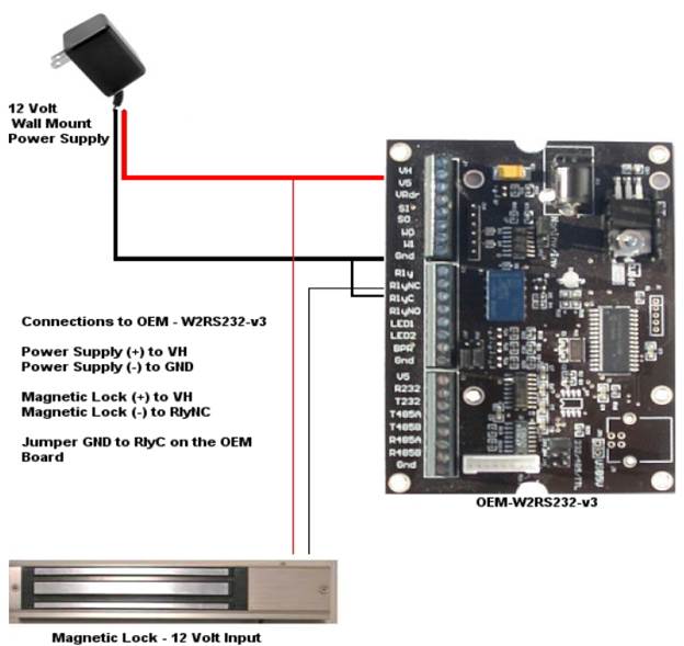
- To control the door lock, you want to switch the negative side of the supply to the electronic lock. Start by connecting the RlyNC to the negative side of the electronic door lock. Next, connect the RlyC to the negative side of the electronic lock’s power supply. Finally, connect the positive of the electronic lock’s supply directly to the lock. You may need to change it to use the RlyNO rather than RlyNC depending on your door lock hardware.
If your door lock can be supplied by 12V DC, reference this example:
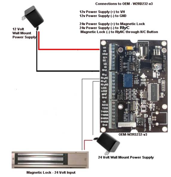
If your door lock does not use 12V or needs its own supply, use this example:
Confirm Serial Connection to Board and Configure Board
- Be sure the EIOBoard Kiosk software is not running if this is a kiosk installation and the EIOBoard Punch service is stopped if this is an EIOBoard Punch installation. Otherwise, the serial port may be in use and locked.
- Download and install the Legacy Door Control Configuration Tool: http://www.rfideas.com/Software/pcProxConfig.exe
- Start the application and it should automatically detect the device if it is successfully connected to the PC.
- Go to the Set Keystroke Data tab, and set the “Send ID Code” checkbox if it is not already set. “Send FAC code” should be unchecked.
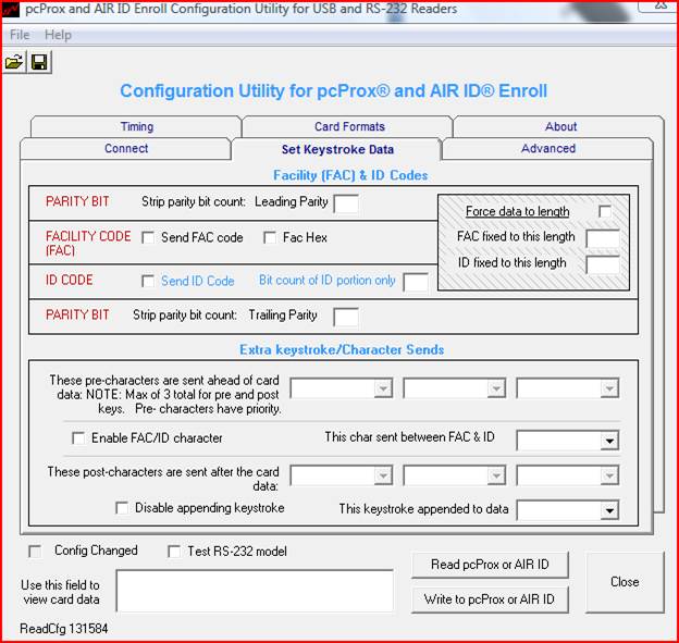
- Click on the Write to pcProx or AIR ID. It should say that the data was written to the pcProx successfully.
- To test the card reader, check the “Test RS-232 model” and then present a badge to the reader. The ID number should show up in the text box below the “Test RS-232 model” checkbox.
- Exit the pcProx Config tool and start the Kiosk software or Punch and configure the Comms to use the PCProx and specify the attached serial port the device is connected to.